
Slicing with Bambu Studio
Source: X2D 3D Printing User Manual · v1.0 · 2026.05 · p. 42–73
5.1 Introduction to Bambu Studio Interface
5.1.1 Homepage
The homepage brings together model management, resource access, and learning guidance. It is the starting point when you open Bambu Studio.
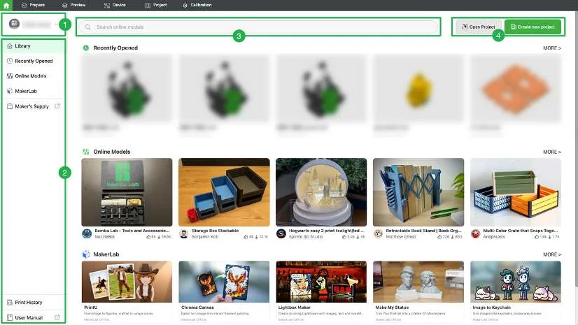
- Account info: View the current account or log out.
- Page navigation: Quickly access recently opened files, online models on MakerWorld, MakerLab, Maker’s Supply, print history, and tutorials.
- Search bar: Enter keywords to search online models on MakerWorld.
- Project operations: Open local projects or create new ones.
5.1.2 Prepare
The Prepare page is used to adjust models, select the printer and filament, set print parameters, slice models, and send print jobs.
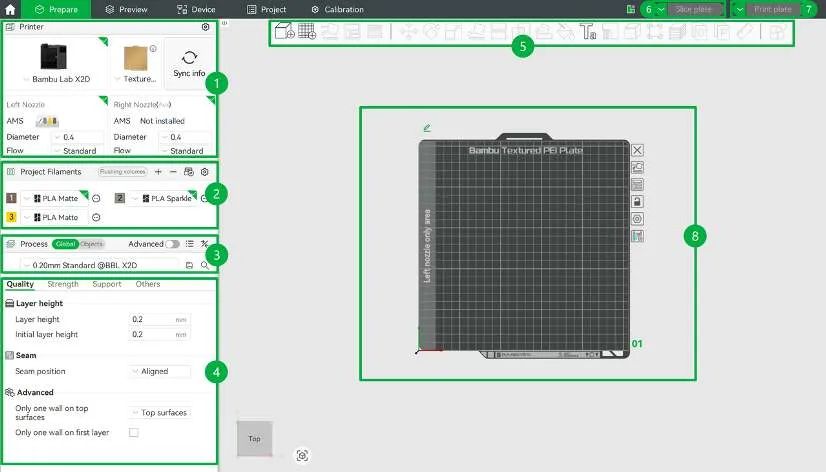
- Printer settings: After selecting a printer model, you can sync the build plate, nozzle, AMS, and filament information with one click. Bambu Studio automatically matches the slicing and print settings based on the selected configuration.
- Filament settings: Displays the filament types and colors used in the current file. Click the + icon to manually add or remove filament. The system automatically loads preset parameters for the selected filament type.
- Process presets: Provides preset parameter combinations for different quality levels, such as Standard and High Quality, which can be applied globally with one click.
- Print parameter details: Models downloaded from MakerWorld usually include complete print parameters and require no additional setup. For special effects, you can adjust the parameters manually (see Adjust Slicing Parameters).
- Top toolbar: After importing a model, select an object to edit and view it using the toolbar (see Use the Top Toolbar).
- Slice button: Click to slice the current plate or all plates and view the slicing results (see Preview). Hover over the button to select the filament grouping mode.
- Print and export: Start printing or export files. Click to choose from the following options:
- Print plate: Start printing the sliced file for the currently selected plate immediately.
- Print all: Send sliced files for all plates to the printer and start printing the last plate immediately. After it finishes, you can select the next plate from Print Files to continue printing.
- Export plate sliced file / all sliced file: Export the sliced files to your computer or a USB drive, then start offline printing from the printer screen via the USB drive.
- Send / Send all: Send the sliced files to the printer’s internal or external storage, such as a USB drive. You can then start the print job manually from the printer screen.
- Print plate: Place and edit models. A project can contain multiple plates.
5.1.3 Preview
The Preview page is used to view slicing results and detailed information for each layer. You can also add custom operations to specific layers.
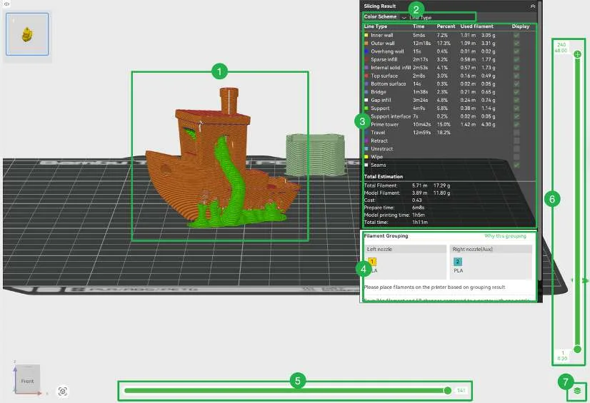
- Model preview: Shows the sliced model. The model colors change automatically based on the selected color scheme. You can view the meaning of each color in the Slicing Result panel.
- Color scheme: Select the type of slicing information to view, such as line type, filament, or print speed.
- Details: Shows detailed information for the selected category, including what each color represents and the corresponding data.
- Filament grouping: View the filament-to-nozzle mapping. If needed, click Regroup filament (see Select Filament Grouping Mode).
- Single-layer path: Drag the progress bar to view the toolhead path on the selected layer.
- Layer details: View the model’s layer count, layer height, and print time. Drag the layer slider to check the slicing results layer by layer. Right-click to add custom operations to a specific layer, such as custom G-code, pause, or filament change.
- Display mode: Switch between viewing all layers and viewing a single layer.
5.1.4 Device
The device interface shows the status of the connected printer and its operation options. You can also perform the same operations on the printer Screen (see Printer Screen Control).
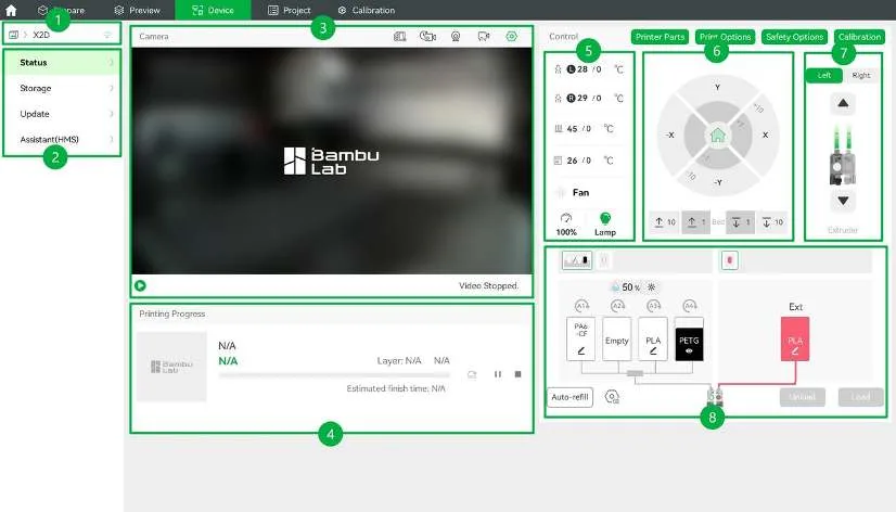
- Device info: Shows the currently connected printer. Tap to switch devices.
- Device status and management: View printer information, including device status, storage media, firmware updates, and the Health Management System (HMS). Supports real-time monitoring, device control, USB file viewing, and firmware updates.
- Live video: Play or pause the live video and manage recording and livestream status.
- Current print job: Displays information about the current print job, including the job thumbnail and print progress. You can skip objects, pause, start, or stop the job.
- Temperature control: Adjust the air management system, and set temperatures for the nozzle, heatbed, and chamber. The number on the left is the current temperature, and the number on the right is the target temperature.
- Motion control: Move the toolhead and heatbed when the printer is idle.
- Extruder control: Shows the extruder feed status. A green dot indicates that the filament is loaded. Use the up and down arrows to manually extrude or retract 1 cm of filament.
- Filament management: View and edit filament information, and control loading, unloading, and Auto Refill. After connecting an AMS, you can also enable Insertion update, Update on startup, Update remaining capacity, and other features.
5.1.5 Project
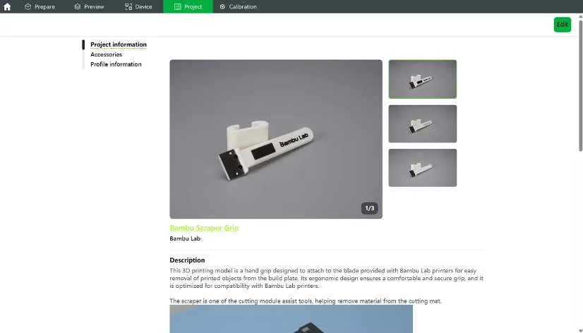
Displays the project information contained in the current 3MF file, including model description, required accessories, and configuration file details.
5.1.6 Calibration
The Calibration page is used to adjust the printer’s extrusion accuracy, ensuring accurate extrusion and stable print quality. Calibration is recommended when changing filament brands or hotends, or when obvious extrusion issues occur. For details, see Filament Calibration.
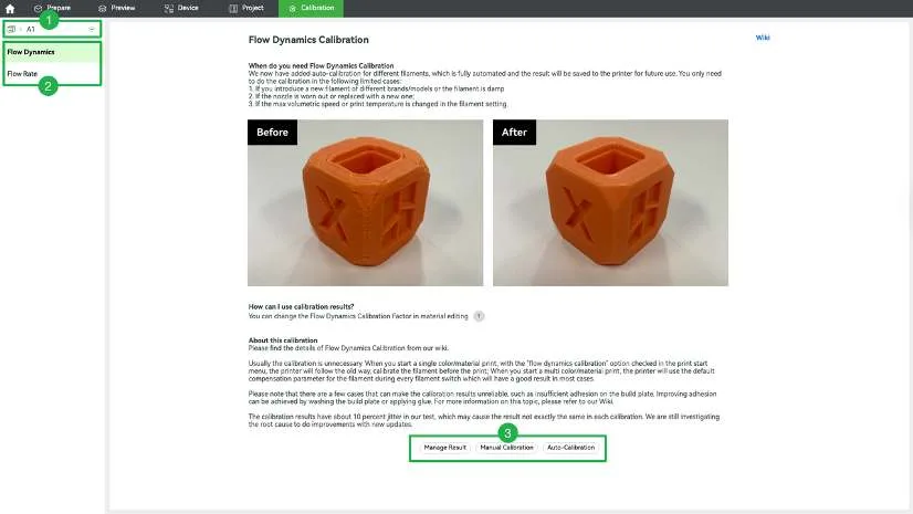
- Printer: Switch printers.
- Calibration type: Choose Flow Dynamics Calibration or Flow Rate Calibration.
- Calibration options: Manage calibration results and perform manual or automatic calibration.
5.2 Use the Top Toolbar
The top toolbar is located at the top of the Prepare page in Bambu Studio. It is used to import models, adjust model position and size, and perform auxiliary operations before printing.

5.2.1 Position and Resize the Model
Add Models
Import 3D model files (such as 3MF, STL, etc.) from your computer.
Operating Steps:
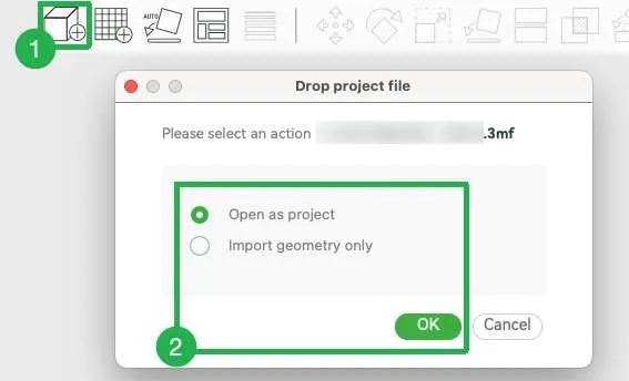
- Click the Add Models icon to select local files.
- If importing a 3MF file, select an action and click OK.
- Open as project: Closes the current project and opens a new one.
- Import geometry only: Imports only the model’s geometry into the current project and ignores print settings.
Add Plate
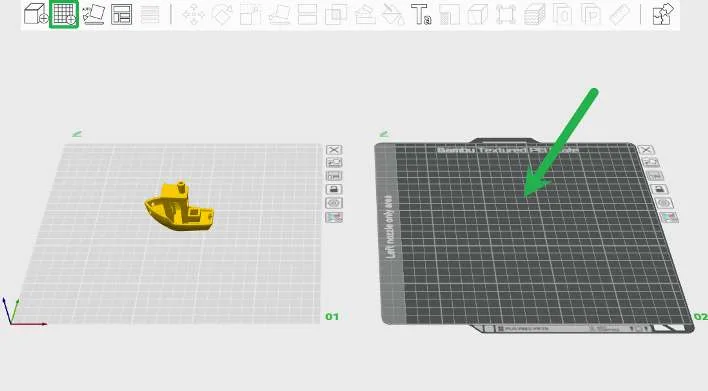
Create 1 new print plate in the current project to place new objects.
Use this when preparing different models separately or applying different settings to the same model.
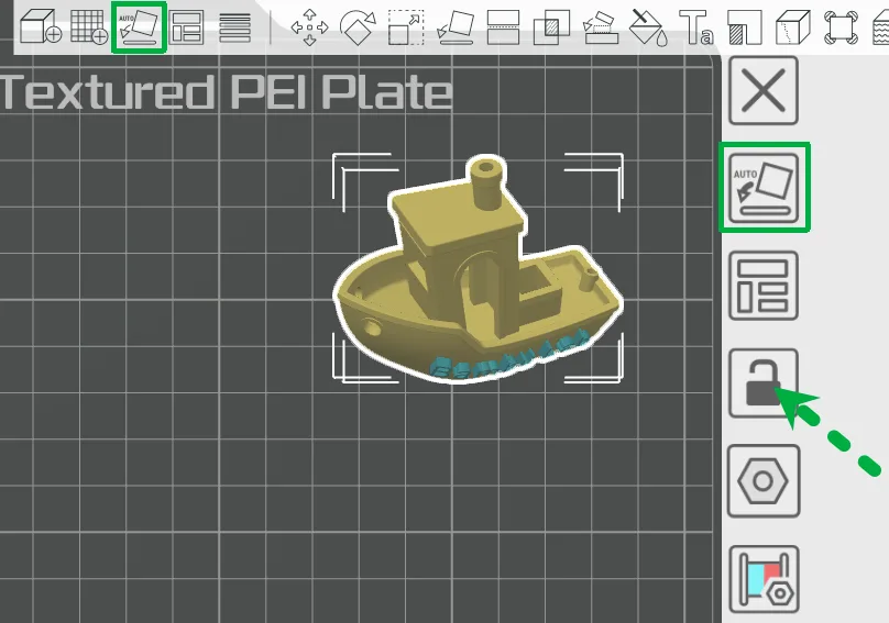
Auto Orient
Automatically adjust the orientation of all objects in the project to improve printability.
Use this feature first if you are unsure how to place objects.
- Adjust all objects in the project: Click the Auto Orient icon in the top toolbar.
- Adjust all objects on a single plate: Click the Auto Orient icon on the right side of the plate.
- Adjust an object: Use the rotate tool to adjust manually (see Rotate for details).
- Adjust all objects on selected plates: Click the lock icon on the right side of the plate to lock plates you don’t need to adjust, then click the Auto Orient icon in the top toolbar.
Arrange All Objects
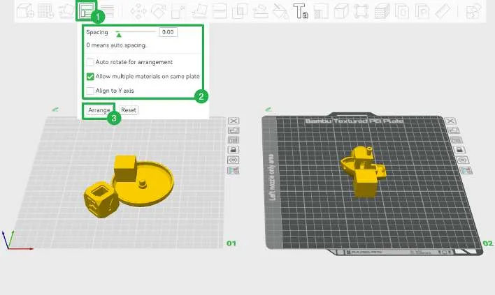
Automatically arrange all objects in the current project to avoid overlap. After importing a model with multiple objects, use this to quickly create an initial layout.
Operating Steps:
- Arrange all objects in the project
- Click the Arrange icon.
- Set placement requirements.
- Click Arrange (Shortcut: A).
-
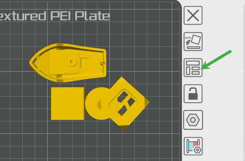
Arrange all objects on the current plate
Click the Arrange icon on the right side of the plate (Shortcut: Shift + A).
-
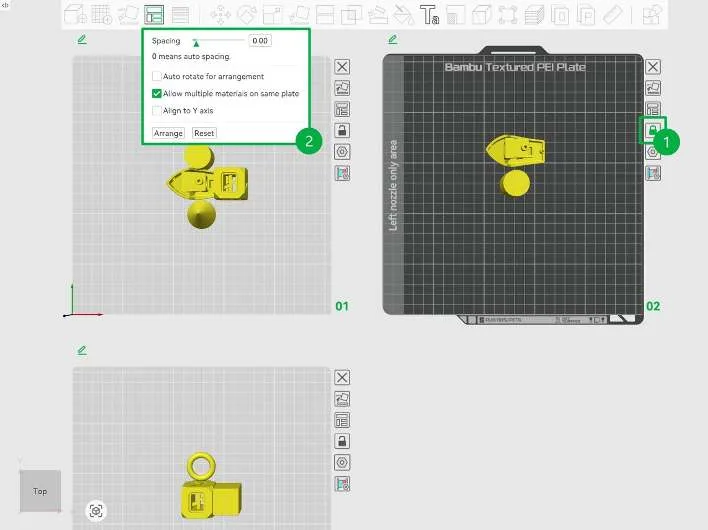
Arrange all objects on selected plates
- Click the lock icon to lock the plates you do not want to arrange.
- Click the Arrange icon. Set placement requirements, then click Arrange.
Move and Align
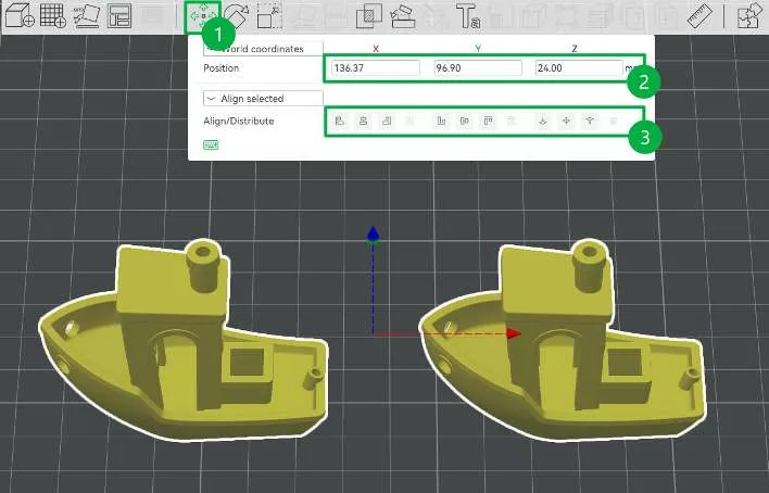
After selecting an object or part, you can drag it directly with the left mouse button or use the Move tool to view and precisely set its position coordinates. You can also select multiple objects to align them as needed, or align multiple parts within a single object.
Operating Steps:
- Click the Move icon.
- Enter a value in the field for precise positioning.
- Align the selected objects or parts.
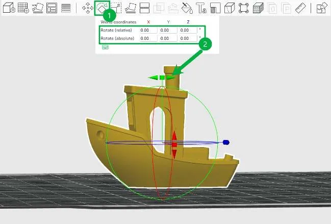
Rotate
Manually adjust the object’s print orientation.
Operating Steps:
- Click the Rotate icon to enter the adjustment interface.
- Drag the endpoints of the X / Y / Z axis to rotate, or enter the rotation angle directly.
Scale
Adjust the overall or local size of an object.
Operating Steps:
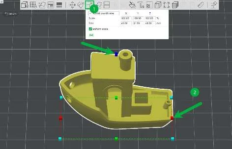
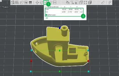
- Click the Scale icon to enter the adjustment interface.
- Choose one method to adjust the size:
- Method 1: Drag the model handles.
- Drag the four bottom corner handles to scale proportionally.
- Drag the other handles to stretch in a single direction.
- Method 2: Enter dimensions or a scale ratio.
- Select Uniform Scale to keep proportions linked when changing any one value.
- Clear it to adjust the X / Y / Z dimensions independently.
- Method 1: Drag the model handles.
Lay on Face
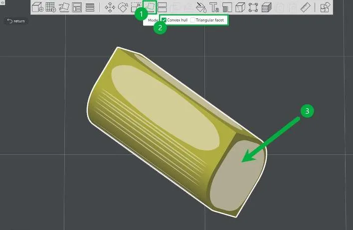
Manually set a selected face of the model as the print base. This feature is useful when Auto Orient does not give the desired result or when a specific face needs to be placed on the build plate.
Operating Steps:
- Click the Lay on Face icon to enter the adjustment interface.
- Choose a display mode: Convex hull or Triangular facet.
- Click the face on the object that you want to use as the bottom face.
Measure
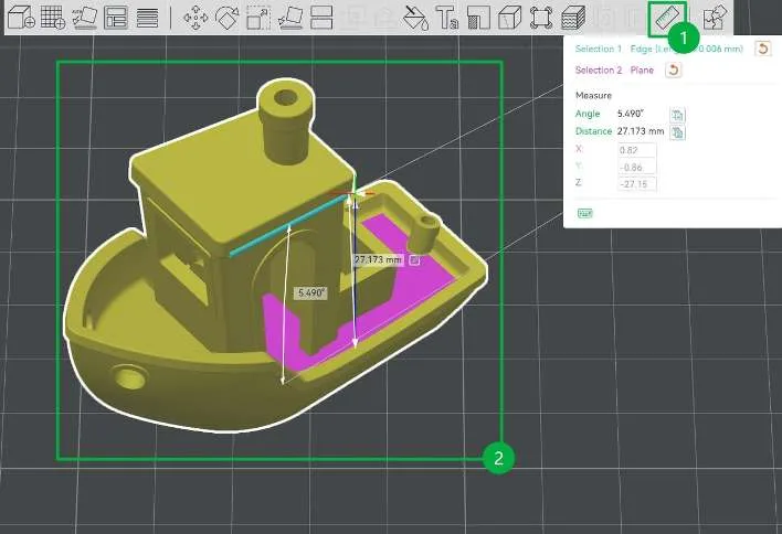
Measure the distance and angle between different positions on the same object or among multiple objects.
This is commonly used to verify if the model dimensions meet expectations before printing.
Operating Steps:
- Click the Measure icon to enter the adjustment interface.
- Select the two measurement ends (such as line segments or faces) in sequence to view the results.
5.2.2 Control Print Quality and Local Features
Variable Layer Height
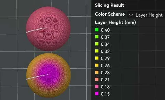
For models with spherical or sloped top surfaces, this feature automatically adjusts the layer height in different height ranges to make the top surface smoother and reduce visible stepping.
It is suitable for models with higher appearance requirements.
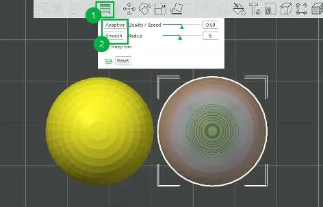
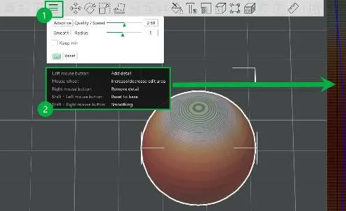
- Click the Variable Layer Height icon to open the adjustment interface.
- Adjust layer height.
- Method 1: Click Adaptive, then click Smooth several times.
- Method 2: Follow the key instructions to adjust the layer height bar on the right and precisely control the layer height at specific positions.
Color Painting
Assign filament colors to the whole object or a specific area, suitable for multi-color printing.
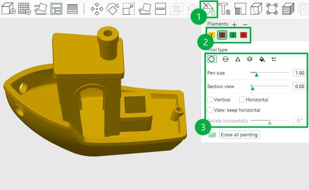
- Click the Color Painting icon to enter the color painting interface.
- Choose a color.
- Select a color painting tool, then adjust the pen size or section view.
- Circle: Paint curved lines on surfaces.
- Sphere: Paint all faces within the spherical area, including hidden faces.
- Triangle: Paint the triangular face under the cursor; drag to paint continuously.
- Height range: Paint all faces within the specified height range.
- Fill: Spread the color from the selected face to connected areas. When Edge detection is enabled, you can set a smart fill angle, and painting will stop at corners sharper than that angle.
- Gap fill: Automatically detect small gaps and fill them with adjacent colors.
Text Shape
Add 3D text to the model surface (supports flat and curved surfaces). Use it for labels, numbers, or descriptive text.
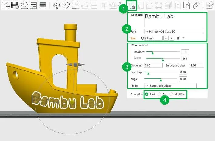
- Click the Text Shape icon to enter the editing interface.
- Enter text and set the font and size.
- Adjust text position.
- Select a generation type:
- Part: Creates an independent solid part, which is sliced as a regular model.
- Cut: Applies a Boolean subtraction to the model to create an engraved effect.
- Modifier: Does not change the geometry. It only modifies print settings, such as color, for the area overlapping the model. This can be used to create 2D text patterns flush with the model surface.
Support Painting
Manually add or block support structures in specific areas by painting on the model.
- In the Support settings under Process, select Enable support and choose a support type.
- Auto: The system generates supports automatically. You can slice the model and check the result before deciding whether manual adjustments are needed.
- Manual: Supports are generated only in painted areas.
- Click the Support Painting icon to enter the support painting interface.
- Select a painting tool and paint on the model:
- Left click: Add supports. The area is shown in blue.
- Right click: Block supports. The area is shown in red.
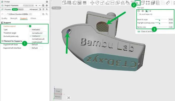
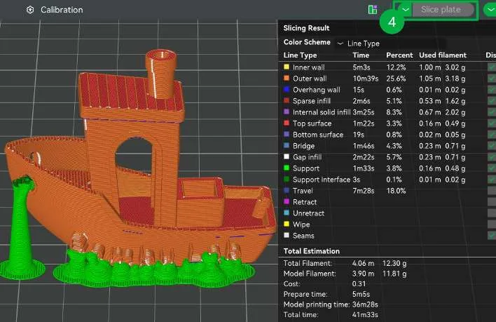
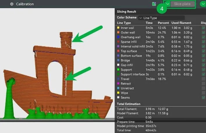
- Click Slice Plate to check the results.
Seam Painting
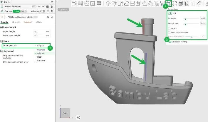
When the automatically generated seam affects appearance, you can manually specify the seam location.
- Set the seam position in the quality settings of the Process panel.
- Click the Seam Painting icon to enter the seam painting interface.
- Select a brush and paint on the model:
- Left-click: Set the Z seam (the area is shown in blue).
- Right-click: Block the Z seam (the area is shown in red).
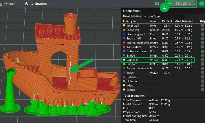
- Click Slice Plate to check the seam result.
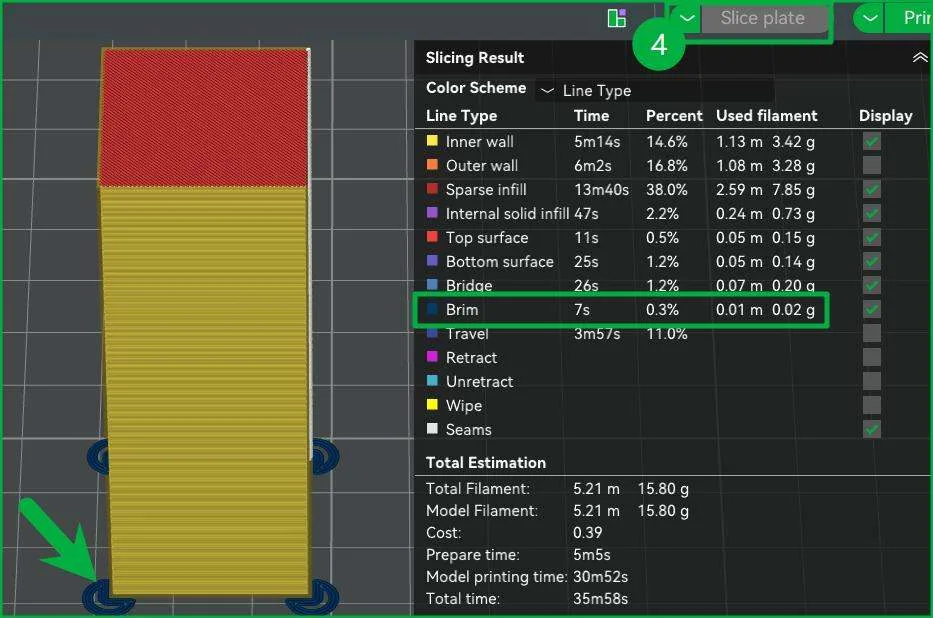
Brim Ears
Generate a brim around sharp corners and other areas to improve adhesion and reduce warping without making removal more difficult. Suitable when you need localized adhesion enhancement without a full brim around the model.
- In the Others section of the Process panel, set Brim Type to Painted.
- Click the Brim Ears icon to enter the brim ears painting interface.
- Select Auto-generate points or manually adjust brim parameters, then left-click to draw at the desired positions.
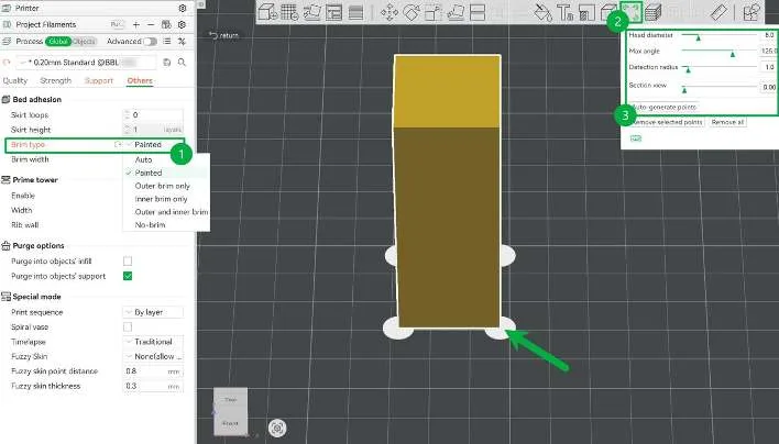
- Click Slice Plate and check the result.
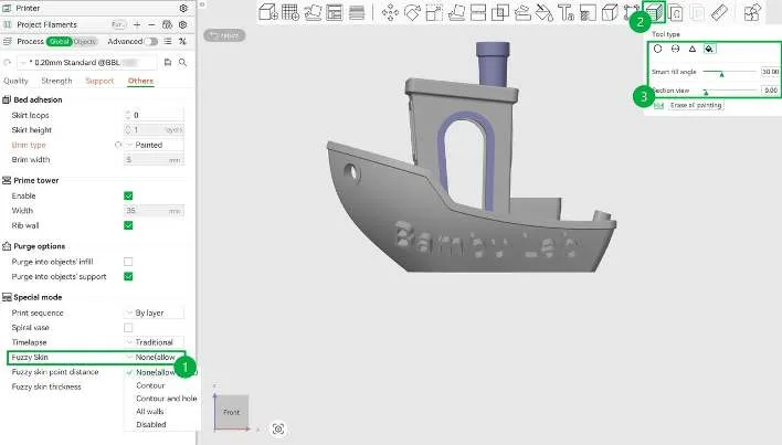
Fuzzy Skin Painting
Create a rough texture similar to animal fur in a specified area by painting. This effect is used for special appearances.
- In the Others section of the Process panel, set Fuzzy Skin to None (allow paint).
- Click the Fuzzy Skin Painting icon to enter the fuzzy skin painting interface.
- Select the painting tool and left-click where you want to paint.
5.2.3 Adjust Model Structure
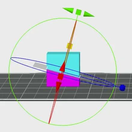
Cut
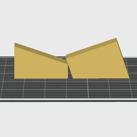
Define a custom cutting plane and cut the model. Common uses include:
- Split an oversized model into parts for printing and assembly.
- Create a flat bottom surface for printing.
- Print only part of the model.
Mesh Boolean
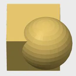
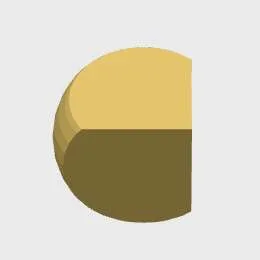
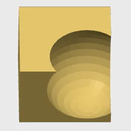
Perform union, intersection, or subtraction operations on multiple objects to generate new models.
Assemble
Quickly align and assemble objects by selecting 2 points or 2 faces without precise coordinate input.
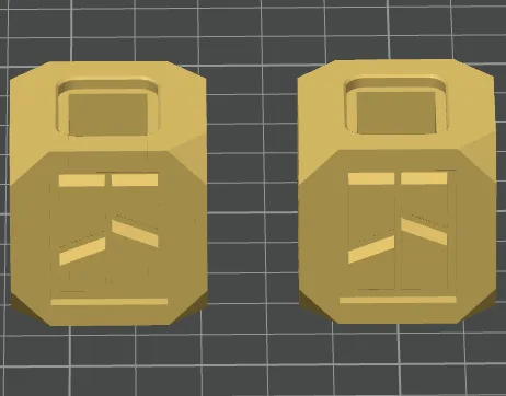
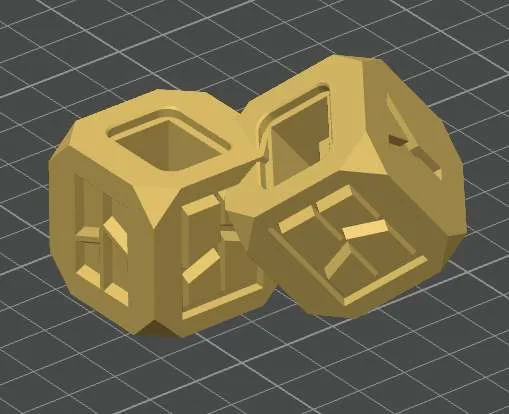
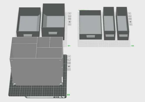
Split to Objects
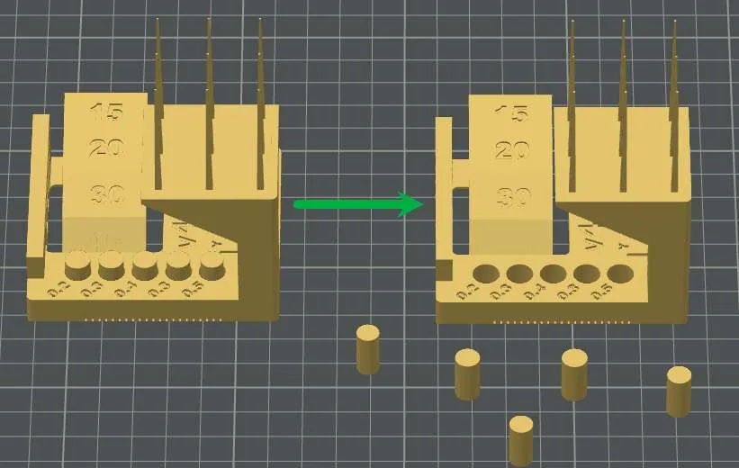
Split 1 object into multiple independent objects. Use this when the model is too large to print or when you need to set different parameters for different parts.
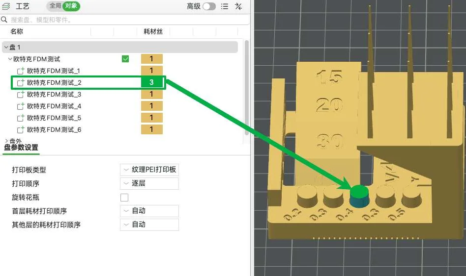
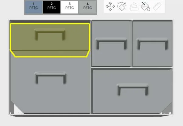
Split to Parts
Keeps the object intact while converting its sections into separate parts, allowing separate filament color settings for each part.
Assembly View
View the alignment and fit of model components. This is only a preview of the assembly and does not modify the model structure.
5.3 Use the Right-Click Menu
On the Prepare page, right-click in the object list or workspace to open a shortcut menu for the current selection.
5.3.1 Right-Click Plate
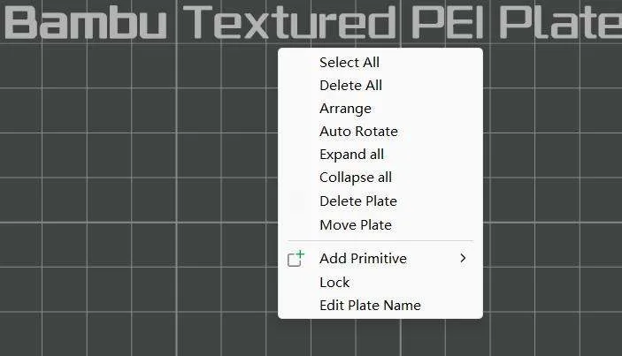
- Select All: Select all objects on the current plate.
- Delete All: Delete all objects on the current plate.
- Arrange / Auto Rotate: Automatically adjust the position and orientation of all objects on the current plate.
- Delete Plate: Delete the current plate. Objects on the plate will move to the off-plate area.
- Move Plate: Changes the number of the current plate, and its position will be updated accordingly.
- Add Primitive: Add a built-in standard model or import an SVG file.
- Lock: Locks the plate. When locked, the Arrange and Auto Orient tools are unavailable.
- Edit Plate Name: Change the name of the current plate.
5.3.2 Right-Click Single Object
Copy and Simplify
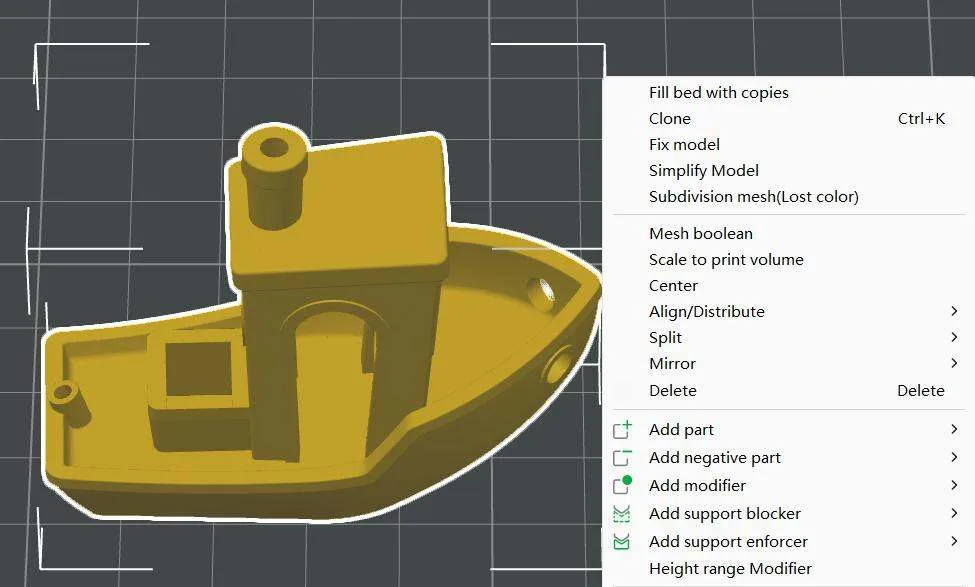
- Fill bed with copies: Automatically clone the selected object to fill the current plate.
- Clone: Select the number of copies and automatically arrange them on the current plate.
- Simplify Model: Adjust the number of triangles in the model to reduce slicing time (this may not shorten print time).
Placement and Transformation
- Center: Move the selected object to the center of the current plate.
- Align/Distribute: Adjust the alignment and distribution of parts within the selected object.
- Split: Divide the selected object into multiple objects or parts. For details, see Adjust Model Structure.
- Mirror: Mirror the object along the X / Y / Z axis.
Local Features
- Add part: Add parts to the selected object.
- Add negative part: Subtract a specified shape from the selected object to create a hollow. Supports cubes, cylinders, spheres, cones, or custom shapes.
- Add modifier: Change print settings in the area where the selected object overlaps with the modifier, such as color, speed, or strength. Supports cubes, cylinders, spheres, cones, or custom shapes.
- Add support blocker: Prevent supports from being generated in the area where the selected object overlaps with the support blocker. Supports cubes, cylinders, spheres, cones, or custom shapes.
- Add support enforcer: Force supports to be generated in the area where the selected object overlaps with the support enforcer. Supports cubes, cylinders, spheres, cones, or custom shapes.
- Height range modifier: Change print settings for a specified height range of the object, such as color, speed, or strength.
5.3.3 Right-Click Multiple Objects
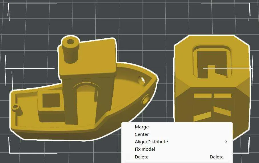
- Merge: Combine multiple objects into 1 object. The original objects remain as parts within the new object.
- Center: Move all selected objects to the center of the current plate.
- Align/Distribute: Adjust the alignment and distribution among the selected objects.
5.4 Adjust Slicing Parameters
5.4.1 Filament Presets
Filament presets include all parameters related to the filament itself during printing, such as temperature, flow rate, and cooling settings.
Use System Filament Presets
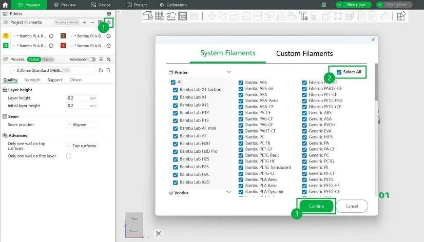
Bambu Studio features built-in official system presets, covering all official filaments and some third-party filaments. You can select all filaments with one click and use the default settings immediately.
Custom Filament Presets
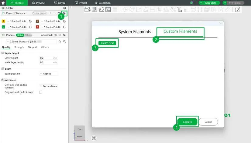
If your filament is not included in the system presets, select the corresponding Generic preset first, then fine-tune it based on the manufacturer’s recommended settings and save it as a custom filament for future use.
5.4.2 Process Preset
Use Default Preset
Process presets include the main settings required for a print job, such as quality, strength, speed, and supports. You can select a system preset from the drop-down menu in the Process panel.

- Layer height: A smaller layer height produces finer detail, but usually increases print time. The default value is 0.2 mm.
- Quality level: Presets are optimized with different priorities. Common types include:
- Standard: Balances print quality, strength, and print time. Suitable for most models and everyday printing.
- High quality: Lowers print speed and acceleration to improve surface quality and detail.
- Compare presets: Select any two to view their settings and see the differences.
Create Custom Preset
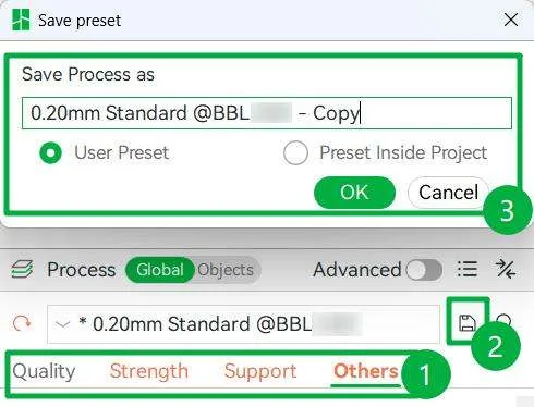
Bambu Studio supports custom presets. For special needs, adjust parameters and save as a new process preset for future use.
5.4.3 Quality Settings
Quality settings affect the model’s detail, surface smoothness, and overall appearance. The system process presets are optimized for most scenarios to provide a good balance between print quality and print time.
For models with higher appearance requirements, such as curved, sloped, or display models, adjust the relevant settings to improve surface finish. If print speed matters more, reduce the level of detail accordingly.
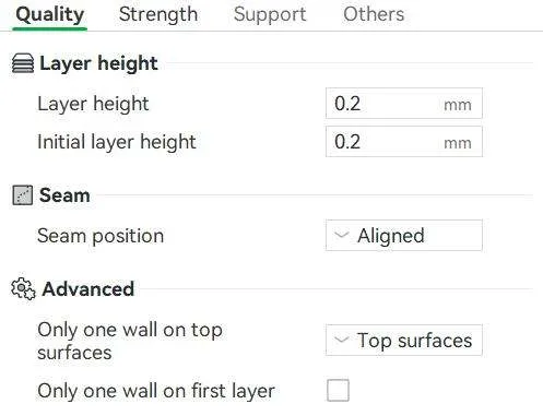
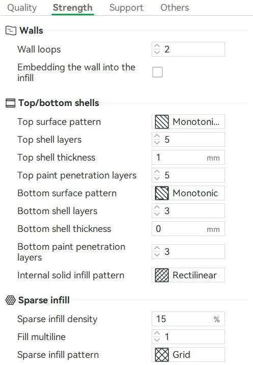
5.4.4 Strength Settings
Print strength determines the model’s sturdiness, durability, and load-bearing capacity. It is mainly affected by wall thickness and the internal structure, such as infill.
The system process presets provide balanced strength settings for common use cases, helping ensure reliable model structure while maintaining print efficiency.
For functional or load-bearing parts, you can increase strength-related settings as needed. For display-only models, no extra reinforcement is required.
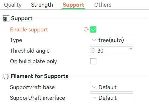
5.4.5 Support Settings
Models with overhangs, bridges, or complex structures usually require support to ensure print stability and prevent collapse during printing. Bambu Studio can automatically generate multiple support types. The default settings work well for most models and balance stability with ease of post-processing.
For models with high surface quality requirements or complex structures, you can adjust the support settings as needed to make supports easier to remove and reduce surface marks.
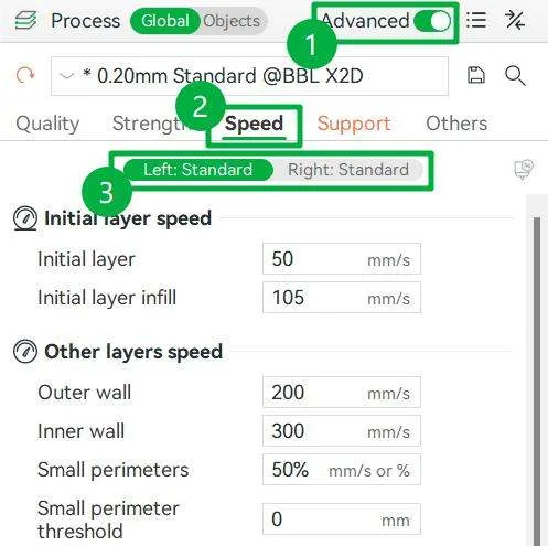
5.4.6 Speed Settings
Print speed affects the stability, surface quality, and efficiency of the print. Speeds that are too fast can cause loss of detail or rough surfaces, while speeds that are too slow significantly increase print time.
The system process presets provide suitable default speed settings for different print tasks and work well for most scenarios.
5.4.7 Adjust Local Parameters
Besides modifying global parameters, you can set parameters and assign filament for specific objects or local areas such as parts, negative parts, or modifiers.
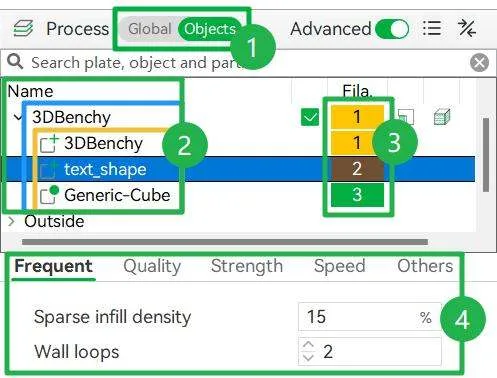
Operating Steps:
- At the top of the process panel on the left, switch to Objects to access the object list.
- Expand the list hierarchy (Print plate > Objects > Parts / Negative Parts / Modifiers), and select the target section to adjust.
- Select dedicated filaments for the target section.
- Modify its printing parameters separately in the list below.
5.5 Check Slicing Result
After slicing, the system automatically switches to the preview page. To ensure successful printing and avoid waste, review the following before starting the print job.
5.5.1 Print Summary
View a summary of the current print job in the slicing results panel.
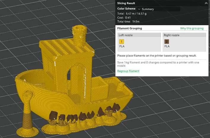
- Filament Usage: The estimated filament length and weight required to print the model.
- Cost Estimate: The estimated print cost, calculated automatically based on the Price in the filament settings.
- Print Time: The estimated total time required to complete the print.
- Filament Grouping: Check the filament-to-nozzle mapping and confirm the actual filament placement. If needed, click Regroup filament. For details, see Select Filament Grouping Mode.
5.5.2 Color Scheme
Use the dropdown menu to check slicing information by different dimensions.
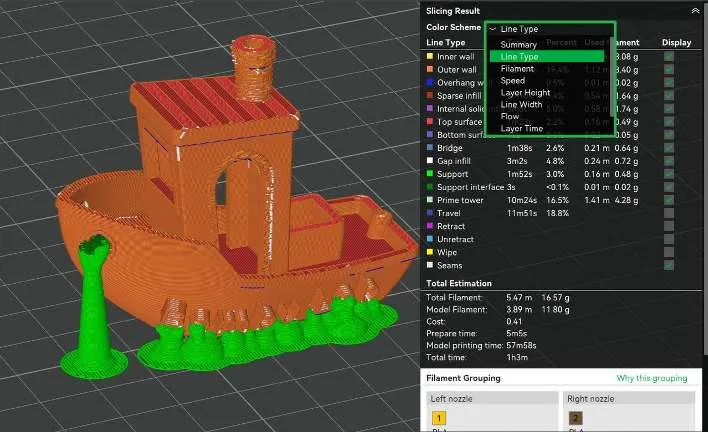
We recommend checking the following information:
- Line Type: Check the distribution of supports, outer walls, and infill, with particular attention to where supports are generated.
- Speed: Observe the toolhead speed at different locations to identify abrupt speed changes.
- Layer Height: Check the effect of variable layer height settings and observe whether the transitions are smooth.
- Flow: Observe whether the filament extrusion volume is evenly distributed.
- Layer Time: Identify areas with short cooling times (such as tips) to prevent overheating and deformation.
5.5.3 Print Path
Use the sliders on the right and bottom of the preview page for detailed inspection:
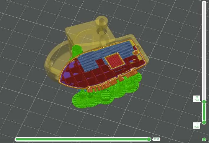
- Vertical Slider: Drag vertically to view the stack of each layer and check internal fill structure or overhangs.
- Horizontal Slider: Simulate the exact toolhead movement on the current layer and verify the start and end points.
5.5.4 Layer Settings
Right-click the + button on the vertical slider to customize the current layer:
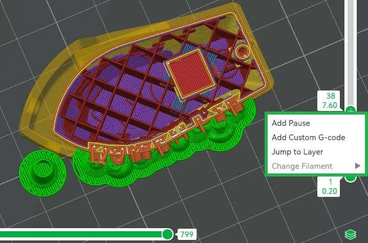
- Add Pause: Pause printing before the selected layer and requires manual resumption. This can be used to embed materials such as magnets into the model.
- Add Custom G-code: Add custom G-code at the selected layer to activate various personalized functions.
- Jump to Layer: Enter a specific layer number to jump precisely to that layer.
- Change Filament: Change the filament at the selected layer. This feature requires using AMS.
5.5.5 Warnings and Tips
If the software detects a potential issue, such as the model not touching the build plate, an excessive overhang angle, or missing supports, a yellow warning icon appears next to the Slice button.
