
Regular Care and Maintenance
Source: X2D 3D Printing User Manual · v1.0 · 2026.05 · p. 136–148
11.1 Regular Maintenance
11.1.1 Maintenance Frequency
The printer can assess its cleanliness based on task type and print duration, and provide maintenance reminders. After receiving the printer, update the firmware to the latest version to enable this feature.
| Component | Type | Frequency | Operating Steps | |
|---|---|---|---|---|
| Printer | Printer system | Calibration | After transport or maintenance | On the printer screen, select ⚙ › Calibration › Print Calibration. |
| Printer Chamber | Live view camera | Clean | 1 month | Wipe with a cotton swab or non-woven cloth dampened with alcohol. |
| Build plate | Clean | 1 week | Wash the surface with warm water and dish detergent, then wipe it dry. | |
| Air filter | Clean | 3 months | Wipe the filter cover with a non-woven cloth dampened with alcohol, and replace the activated carbon filter regularly. | |
| Bottom and lining | Clean | 1 month | Brush off filament debris and foreign objects, then wipe with a non-woven cloth dampened with alcohol. | |
| XYZ axes | X-Axis | Clean and Lubricate | 1 month | Wipe with a non-woven cloth dampened with alcohol, then apply lubricant grease to the lead screws and lubricant oil to the linear rods after cleaning. |
| Y-Axis | ||||
| Z-Axis | 3 months | |||
| Toolhead | Toolhead camera | Clean | 1 month | Wipe with a cotton swab or non-woven cloth dampened with alcohol. |
| Extruder | Clean and Lubricate | Remove internal debris and apply lubricant grease to the gears. | ||
| Hotend | Clean | Cold pull. | ||
11.1.2 Print Calibration
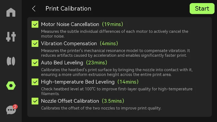
To ensure printing accuracy and stable operation, perform a full calibration after moving the printer or maintaining key components such as the XYZ axes, belts, and toolhead.
On the printer screen, tap ⚙ › Calibration › Print Calibration, then select the calibration task as needed.
11.1.3 Air Filter
Tools: non-woven cloth, alcohol, dust brush, and a new activated carbon filter.
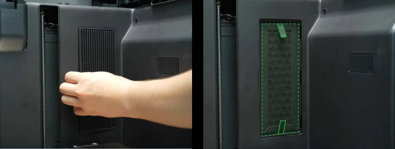
Regularly clean dust from the air filter cover. If the filter surface is visibly dirty or saturated, replace the activated carbon filter.
-
On the printer touchscreen, tap ⚙ › Motion › heatbed ↓ to lower the heatbed to the bottom.
-
Remove the filter cover from the side clips. Use a dust brush to clean the surface, then wipe it with a non-woven cloth dampened with alcohol.
-
Hold the filter handles and pull outward to remove it, then install a new filter.
11.1.4 XYZ Axes
Clean and Lubricate the X-Axis
Tools: non-woven cloth, alcohol, lubricant oil.
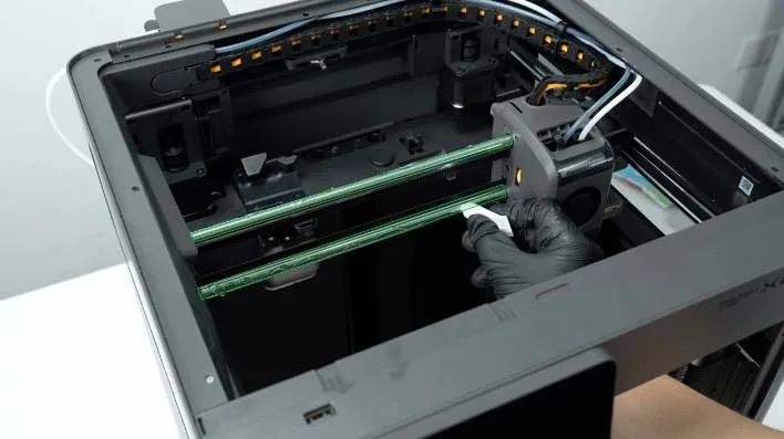
- Use a non-woven cloth dampened with alcohol to wipe the X-axis linear rods and X belts.
- Move the toolhead to clean the remaining parts.
- Apply lubricant oil dropwise onto the linear rod. Manually move the toolhead along the X-axis slowly 3 to 5 times to ensure even distribution.
Clean and Lubricate the Y-Axis
Tools: Non-woven cloth, alcohol, lubricant oil.
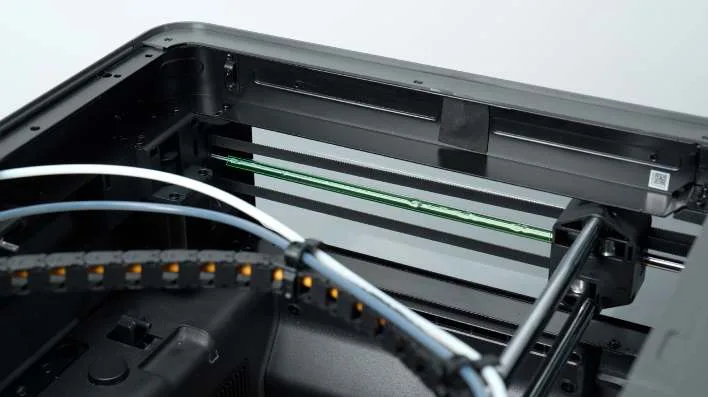
- Use a non-woven cloth dampened with alcohol to wipe the Y-axis linear rods on both sides.
- Move the toolhead to clean the remaining parts.
- Apply lubricant oil dropwise onto the linear rods. Manually move the toolhead along the Y-axis 3 to 5 times to ensure even distribution.
Clean and Lubricate the Z-Axis
Tools: Non-woven cloth, alcohol, lubricant oil.
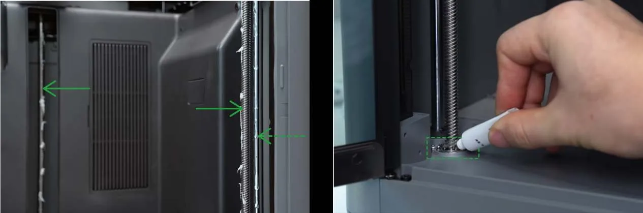
The Z-axis includes three sets of lead screws and smooth rods: one at the left front, one at the right front, and one at the rear center. The front sets include both a lead screw and a smooth rod, while the rear set includes only a lead screw. During cleaning, raise the heatbed from the printer screen to access the lower sections.
- Use a non-woven cloth dampened with alcohol to wipe the lead screws and linear rods on both sides and at the rear.
- Apply lubricant oil to the linear rods shown with dashed lines and to the bearings at the bottom of the lead screws. Apply lubricant grease to the lead screw bodies shown with solid lines.
- Connect the power. On the printer screen, tap ⚙ › Motion, then move the heatbed up and down 3 to 5 times to spread the lubricant evenly.
11.1.5 Heatbed
Tools: non-woven cloth, alcohol.
-
On the printer screen, tap ⚙ › Motion › ▲ to raise the heatbed. Clean any leftover filament underneath.
-
Spray alcohol evenly on the bottom of the chamber, then wipe clean with a non-woven cloth.
-
On the printer screen, lower the heatbed and remove the build plate. Use a non-woven cloth dampened with alcohol to wipe the heatbed surface.
-
After the alcohol has fully evaporated, place the build plate back properly.
11.1.6 Build Plate
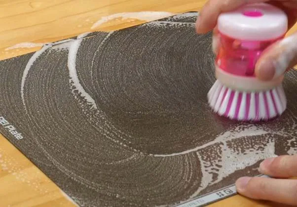
Tools: dish detergent, sponge or brush.
Wash the build plate with warm water and dish detergent. Dry it completely before attaching it to the heatbed for use.
11.1.7 Toolhead
Tools: pointed tweezers, H2.0 and H1.5 allen keys, lubricant grease.
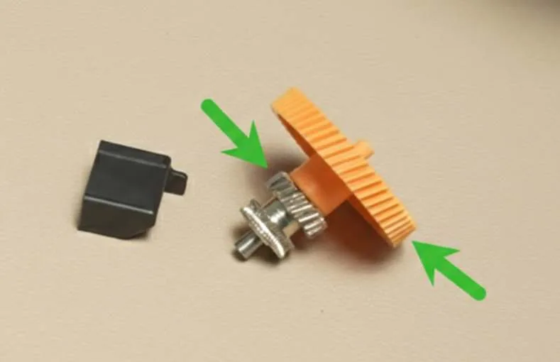
The gear assembly inside the extruder may wear after prolonged use, causing printing issues. Regularly apply lubricant to ensure smooth printing.
- Remove the extruder, detach the Hall sensor assembly, then separate the extruder gear components.
- Apply lubricant grease to the 2 gear locations shown in the illustration.
11.1.8 Camera
Tools: cotton swab (or non-woven cloth), alcohol.
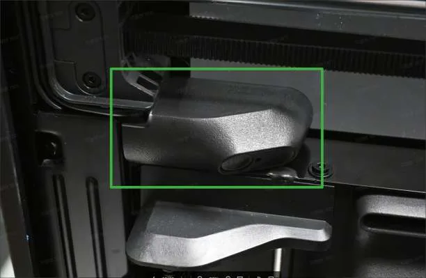
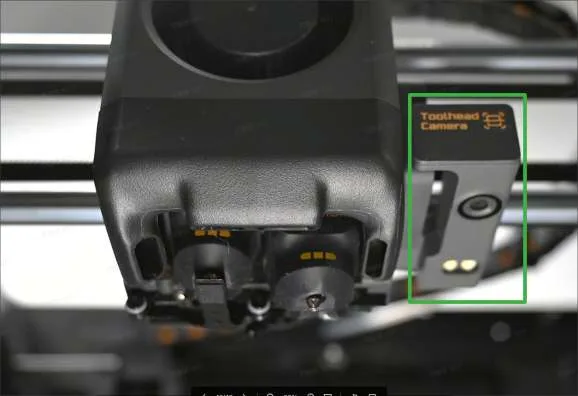
After prolonged use, volatile particles may build up on the surfaces of the live view camera and toolhead camera. This causes blurry video and reduces visual detection sensitivity.
Dip a cotton swab in a small amount of alcohol and wipe the camera surfaces.
11.2 Replace Accessories
Over time, wear or aging of certain printer accessories can affect overall printing performance. Regularly check the condition of accessories and replace them as needed. This chapter explains the replacement requirements and steps for common consumable parts. You can also visit the Bambu Lab Wiki and see “Part Replacement Guide” for more tutorials.
11.2.1 Hotend Silicone Sock
Tools: spare silicone sock (included in the toolbox).
The silicone sock is installed around the hotend nozzle to maintain a stable nozzle temperature. Replace it if it is damaged or no longer stays securely in place.
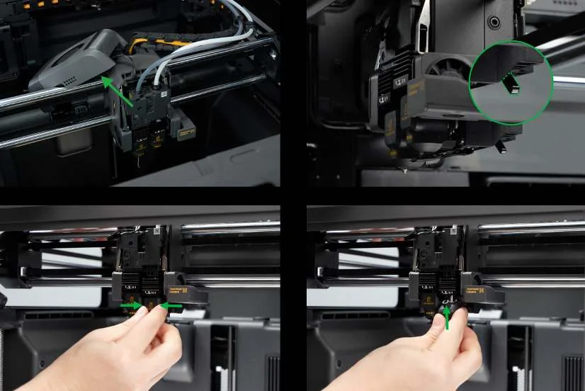
- Remove the toolhead front cover and hang it aside.
- Toggle the nozzle switching lever to position the flow blocker under the other hotend.
- Pinch the top of the silicone sock and pull it down diagonally to remove.
- Install the replacement silicone sock onto the hotend from bottom to top.
- Gently pull on the silicone sock to ensure it fits properly, then snap the toolhead front cover back into place.
11.2.2 Hotend
Tools: replacement hotend, heat-resistant gloves.
Replace the hotend when it is clogged or damaged and standard unclogging steps (see Hotend Unclogging) can no longer resolve the issue.
-
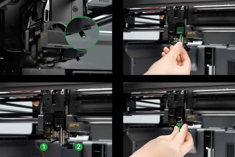
Remove the toolhead front cover. Move the nozzle switching lever to position the flow blocker under the other hotend.
-
Remove the hotend silicone sock. Then open the hotend locking tabs, right first and then left, and remove the hotend.
-
Insert the replacement hotend. Secure the hotend locking tabs, left first and then right, ensuring they fit snugly.
-
Reinstall the silicone sock and the toolhead front cover.
11.2.3 Nozzle Wiping Pad
Tools: nozzle wiping pad (included in the accessory box).
The nozzle wiping pad is installed on the purge wiper and is used to remove residual waste material from the nozzle surface. Replace it when it is damaged or dislodged.
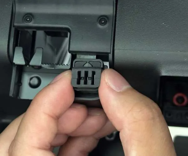
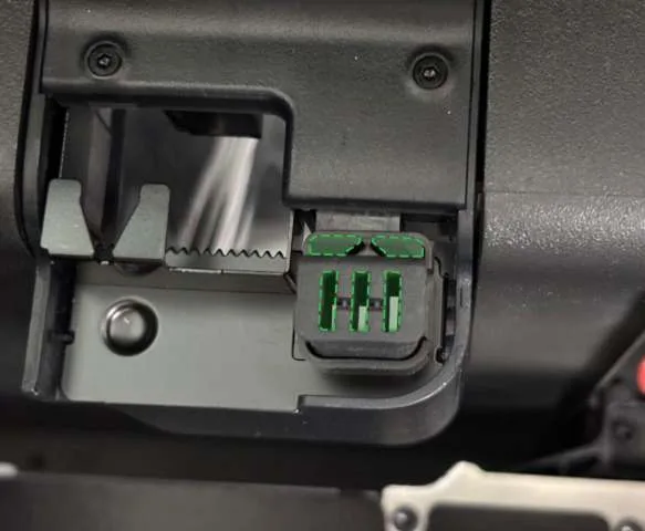
- Remove the old nozzle wiping pad from the purge wiper.
- Insert the spare nozzle wiping pad. Align the nozzle wiping pad with the groove on the purge wiper, then press down until it is installed securely.
11.2.4 Flow Blocker
Tools: allen key H1.5, flow blocker (included in the toolbox).
The flow blocker blocks the idle nozzle to prevent filament leakage. Replace it if it is deformed and cannot be manually adjusted or repaired.
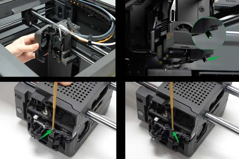
- Remove the toolhead front cover.
- Move the nozzle switch lever to the left to position the flow blocker under the left-side nozzle.
- Loosen the screw from the rear of the toolhead and remove the flow blocker.
- Replace the flow blocker and tighten the screw securely.
- Snap the toolhead front cover back into place.
11.2.5 Left and Right Filament Cutters
Tools: allen key H1.5, left and right filament cutters (included in the toolbox), needle-nose pliers, or tweezers.
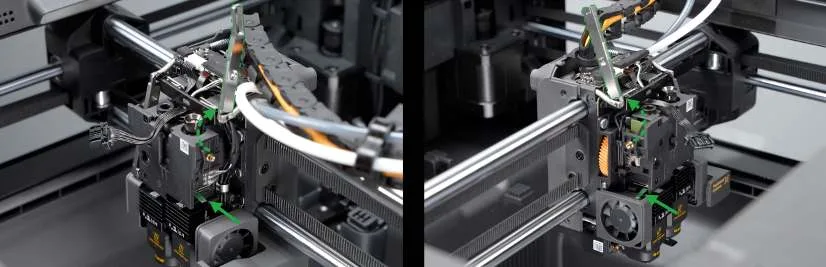
The filament cutter is inside the toolhead and connected to the filament cutter lever. During filament unloading or changing, the cutter lever drives the cutter to cut the filament for the corresponding hotend. If unloading failures occur frequently when using AMS, check whether the blade has become dull first.
Visit the Bambu Lab Wiki and search for “filament cutter replacement guide for X2D” for detailed replacement instructions.
11.2.6 PTFE Tube Locking Nut
Tools: open-end wrench, PTFE tube locking nut (included in the toolbox).
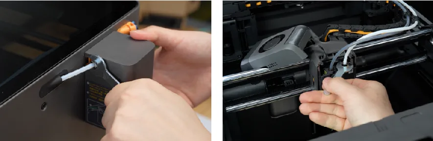
The PTFE tube locking nut secures both ends of the PTFE tube between the auxiliary extruder and the toolhead filament inlet. Replace it with a spare nut if lost.
Use the wrench to tighten the nut clockwise and loosen it counterclockwise.
Enjoy!
The manual is subject to change without notice. Visit the Bambu Lab website for the latest version: bambulab.com/support/documentation.